2.21 Inspect Battery
Fragment manuala — str. 68–70
📋 Tekst do skopiowania (OCR/wyszukiwanie)
INSPECT BATTERY 2.21
PREPARE 4. Connect starter cable.
1. Remove skid plate. See SKID PLATE (Page 3-92). a. See Figure 2-40. Connect starter cable (1) to starter
solenoid (2). Tighten.
2. Disconnect negative battery cable. See POWER Torque: 27--41 in-lbs (3--4.6 N·m) Starter cable nut
DISCONNECT (Page 8-4).
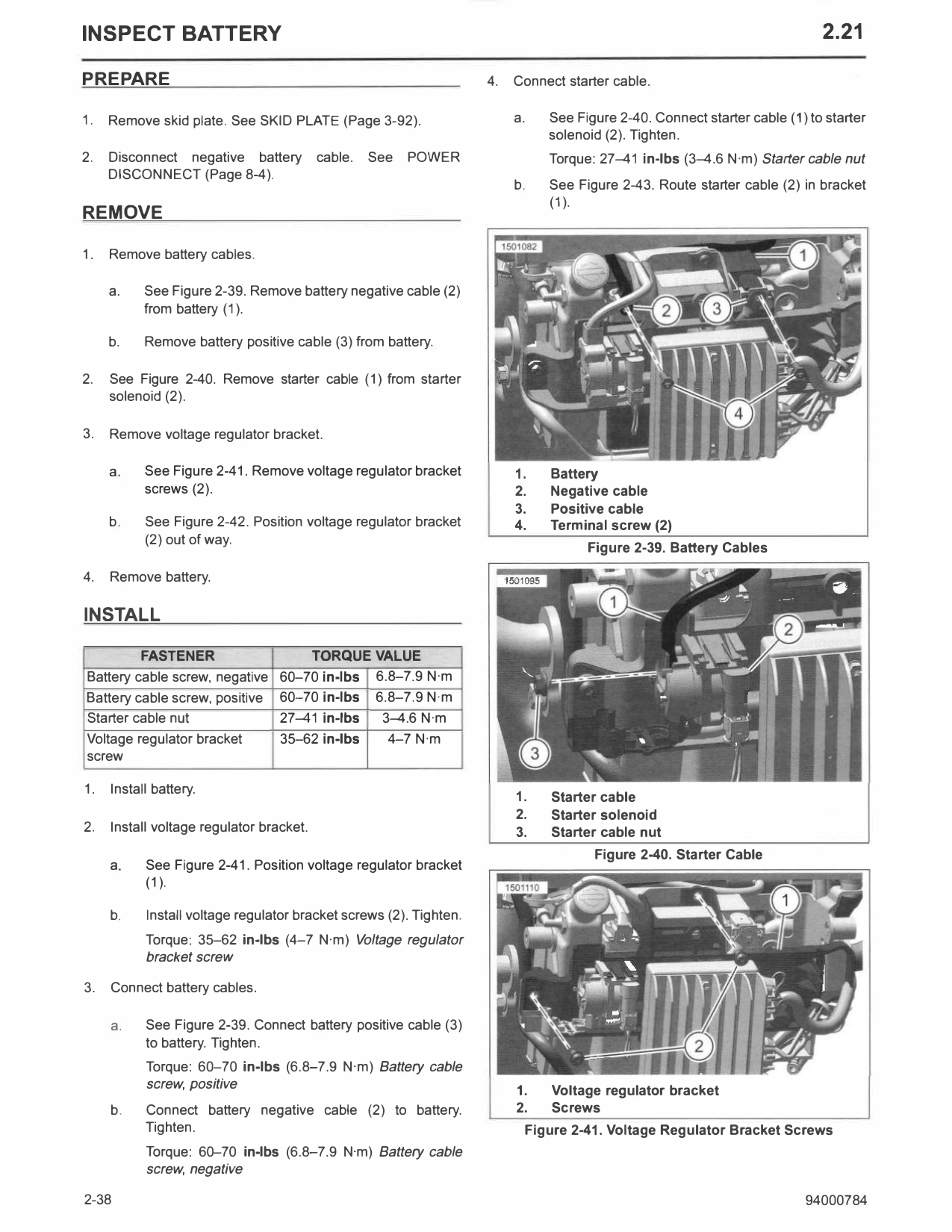
b. See Figure 2-43. Route starter cable (2) in bracket
(1 ).
REMOVE
1. Remove battery cables.
a. See Figure 2-39. Remove battery negative cable (2)
from battery (1).
b. Remove battery positive cable (3) from battery.
2. See Figure 2-40. Remove starter cable ( 1) from starter
solenoid (2).
3. Remove voltage regulator bracket.
a. See Figure 2-41. Remove voltage regulator bracket 1. Battery
screws (2). 2. Negative cable
3. Positive cable
b. See Figure 2-42. Position voltage regulator bracket 4. Terminal screw (2)
(2) out of way.
Figure 2-39. Battery Cables
4. Remove battery.
INSTALL
FASTENER TORQUE VALUE
Battery cable screw, negative 60-70 in-lbs 6.8-7.9 N·m
Battery cable screw, positive 60-70 in-lbs 6.8-7.9 N·m
Starter cable nut 27--41 in-lbs 3--4.6 N·m
Voltage regulator bracket 35-62 in-lbs 4-7 N·m
screw
1. Install battery.
1. Starter cable
2. Starter solenoid
2. Install voltage regulator bracket. 3. Starter cable nut
Figure 2-40. Starter Cable
a. See Figure 2-41. Position voltage regulator bracket
(1 ).
b. Install voltage regulator bracket screws (2). Tighten.
Torque: 35-62 in-lbs (4-7 N·m) Voltage regulator
bracket screw
3. Connect battery cables.
a. See Figure 2-39. Connect battery positive cable (3)
to battery. Tighten.
Torque: 60-70 in-lbs (6.8-7.9 N·m) Battery cable
screw, positive 1. Voltage regulator bracket
b. Connect battery negative cable (2) to battery. 2. Screws
Tighten. Figure 2-41. Voltage Regulator Bracket Screws
Torque: 60-70 in-lbs (6.8-7.9 N·m) Battery cable
screw, negative
2-38 94000784
VOLTAGE TEST
T he voltage test provides a general indicator of battery
condition. Check the voltage of the battery to verify that it is
fully charged. Refer to Table 2-20.
1. If the open circuit (disconnected) voltage reading is below
12.6V:
a. Charge the battery.
b. Check the voltage after the battery has set for at least
one hour.
2. If the voltage reading is 12.7Var above:
a. Perform a battery diagnostic test. See the electrical
diagnostic manual for the load test procedure.
Table 2-20. Voltage Test For Battery Charge Conditions
1. Battery VOLTAGE (OCV) STATE OF CHARGE
2. Voltage Regulator Bracket 12.7V 100%
Figure 2-42. Voltage Regulator Bracket 12.6V 75%
12.3V 50%
12.0 V 25%
11.8 V 0%
STORAGE
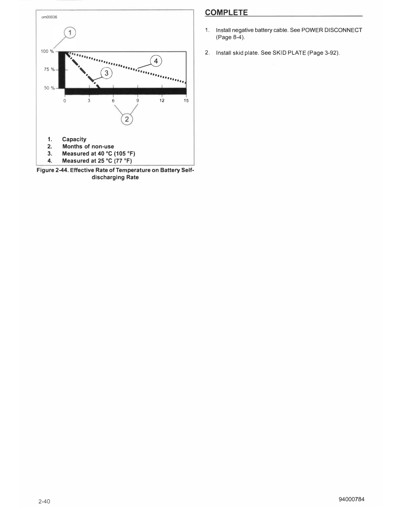
See Figure 2-44. A battery is affected by self-discharge whether
stored in or out of the vehicle. A battery that is stored in the
vehicle is also affected by parasitic loads. A parasitic load is
caused by things like diode leakage or maintaining computer
memory with the vehicle turned off.
Batteries self-discharge at a faster rate at higher ambient
temperatures. Store battery in a cool, dry place to reduce the
self-discharge rate.
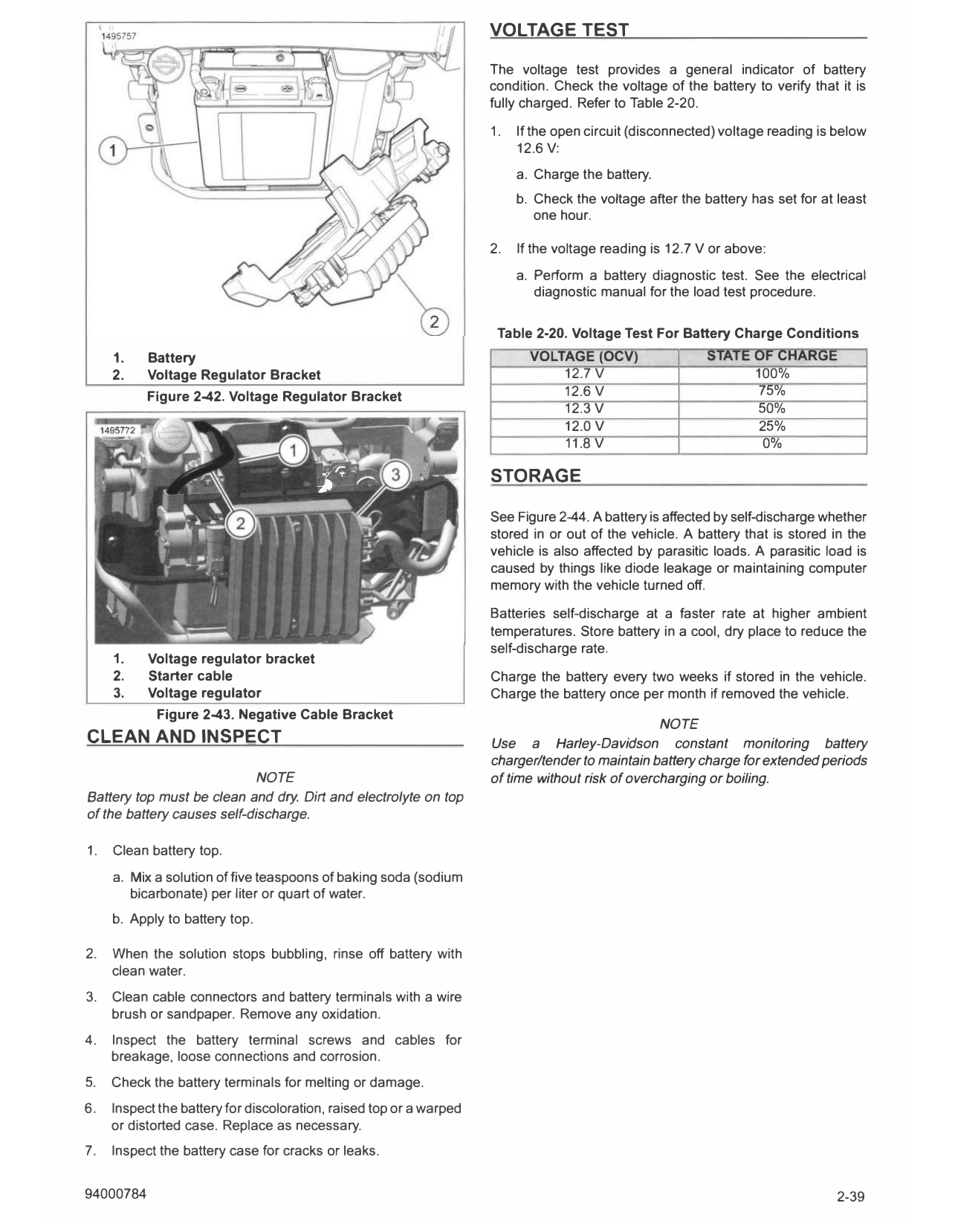
1. Voltage regulator bracket
2. Starter cable Charge the battery every two weeks if stored in the vehicle.
3. Voltage regulator Charge the battery once per month if removed the vehicle.
Figure 2-43. Negative Cable Bracket
NOTE
CLEAN AND INSPECT Use a Harley-Davidson constant monitoring battery
charger/tender to maintain battery charge for extended periods
NOTE of time without risk of overcharging or boiling.
Battery top must be clean and dry. Dirt and electrolyte on top
of the battery causes self-discharge.
1. Clean battery top.
a. Mix a solution of five teaspoons of baking soda (sodium
bicarbonate) per liter or quart of water.
b. Apply to battery top.
2. When the solution stops bubbling, rinse off battery with
clean water.
3. Clean cable connectors and battery terminals with a wire
brush or sandpaper. Remove any oxidation.
4. Inspect the battery terminal screws and cables for
breakage, loose connections and corrosion.
5. Check the battery terminals for melting or damage.
6. Inspect the battery for discoloration, raised top or a warped
or distorted case. Replace as necessary.
7. Inspect the battery case for cracks or leaks.
94000784 2-39
om00036
COMPLETE
1. Install negative battery cable. See POWER DISCONNECT
(Page 8-4).
100 %
•••••••••• ,,,, 2. Install skid plate. See SKID PLATE (Page 3-92).
__0 4
·,JD ············ ..,,,,,,..,
·
·, •••
.
75 %
# •• •••
50 %
0 3 6 9 12 15
1. Capacity
2. Months of non-use
3. Measured at 40 °c (105 °F)
4. Measured at 25 °C (77 °F)
Figure 2-44. Effective Rate of Temperature on Battery Self
discharging Rate
2-40 94000784